Final Drives
The intent of this article is to augment the information that has been written recently regarding the design (and failures) of the final drive gearboxes used on K and R models from the 1980s through the last R1150 models.
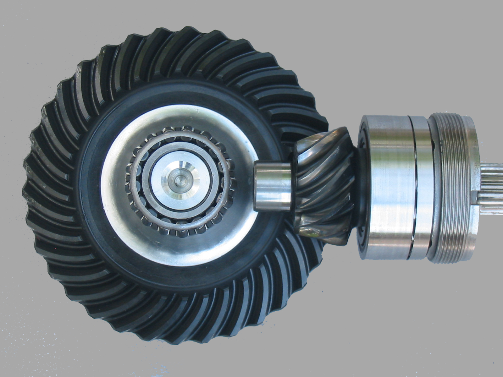
There are basically two moving parts within a final drive. The pinion gear is driven by the driveshaft and usually has ten or eleven teeth. The ring gear (sometimes called the crown gear) is driven by the pinion gear and has about thirty teeth. Each is machined as a shaft which is supported by a bearing on each side of the gear.
When the R80G/S was launched, it brought with it a new final drive design which immediately became as significant a recognition feature as the opposed cylinders had been. The single-sided swingarm, where the wheel bolts on as it does in a car, was here.
Prior to this, the wheel had ridden on an axle which was supported at each end. The power was delivered by a hollow spline which fit around the axle and was supported by its own bearings within the final drive. With the new Monolever design, the drive spline was gone and the wheel fastened directly to the ring gear of the final drive. The axle was eliminated, or more precisely, the ring gear now served as the axle. This meant that the bearings supporting that gear now needed to be strong enough to support the weight of the bike. The Paralever bikes, which started in 1987 and continued through the R1150GS Adventure, used the exact same design.
Here’s how the bearings are arranged in these final drives:
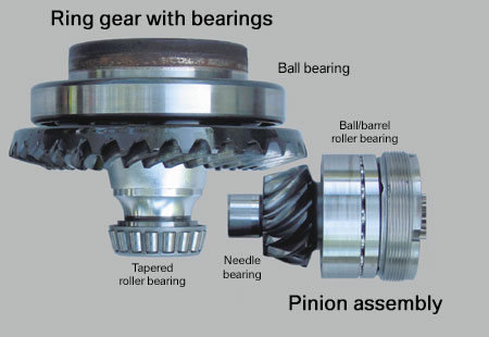
The pinion shaft is held by needle bearings on the inner end and a heavy roller/ball combination bearing on the outside. Because the teeth are helically cut, there is some axial* load on the pinion shaft as it tries to screw itself in or out, but most of the load is sideways: it pushes up and down on the ring gear and tries to push itself away from it due to the angled gear teeth. Since needle bearings cannot resist any axial load, the large bearing is the only thing keeping the pinion from sliding back and forth.
The ring gear is supported by a tapered roller bearing on the inside and a heavy ball bearing on the outside. The main loads are borne by the ball bearing, and the tapered bearing holds the end of the shaft in alignment. In order to properly maintain the gear mesh, it’s vital that the ring gear stay at a controlled distance from the pinion, so it is slightly compressed between these two bearings when the drive is assembled.
There is a problem, though. As it is compressed between the housing and the housing cover during assembly, the ball bearing is axially loaded. Ball bearings generally do not withstand axial loads very well, and most failed bearings show signs of excessive axial loading. Some of this is inherent in the fact that the ring gear is compressed, or preloaded, on assembly, some of it is due to the axial forces from the pinion shaft, and some is from the reaction at the tapered bearing when load is placed on the wheel. Why do we hear more about failures now, if the same design has been used for more than two decades? Let’s take a closer look at the forces on the bearings as bikes get heavier and tires get wider.
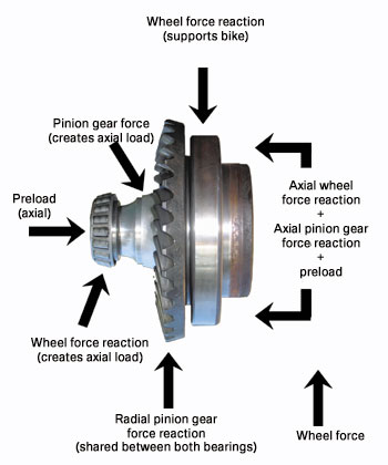
The arrows marked "Wheel force" are from the static load of the bike. There is an upward force from the ground acting through the wheel, several inches away from the final drive. This is countered by a force acting downward on the large bearing (think of this as the weight of the bike) and another force at the tapered bearing, countering the twisting effect which results from the contact patch not being directly under the big bearing. As tires get wider, the contact patch gets farther away and this last arrow gets larger. As it gets larger, the axial component of the force on the tapered bearing grows also, which results in a corresponding axial load on the ball bearing. For a 400-pound load on the wheel of an R1100RT, the horizontal component is about 175 pounds.
The arrows marked "Preload" are the compressive forces resultant from the specified assembly stress. These are constant, and I estimate them at several hundred pounds.
The "Pinion force" arrows represent the force of the pinion gear pushing on the ring gear to make it turn. This is angled due to the shape of the gear teeth, and therefore exerts an axial force on the ring gear which is resisted by the big bearing. When coasting, this force is nearly nothing, but under full acceleration it can be well over 1000 pounds.
This can be seen by looking at the three loads on the far left of the diagram. Each of them tries to push the ring gear to the right, which beans the ball bearing has to push back.
So the big bearing has to resist three different lateral loads for which it isn't so well suited. Are we doomed to suffer bearing failures because the design places axial loads on a ball bearing? No. This is a lifetime (200k mile or more) bearing in most bikes. When it isn’t, something is wrong, and the main variable in the system is the amount of preload on that bearing. The preload is set by shims which fit between the cover and the bearing, and BMW specifies that there should be 0.05~0.10mm of interference when assembling the final drive. If there is too much, you will place excessive side loads on that bearing. What happens to this interference when the unit is assembled? It causes a minute amount of ‘stretch’ of the housing and cover, which is in turn relieved by expansion as the final drive heats up in use.
Many articles have been written about replacing the bearing, but most of them suggest replacing the shims exactly as found. I don’t understand this at all; here is an assembly which has failed and we’re going to replace the damaged component and pretend it never happened? It didn’t go bad by itself. The new 17-ball bearing is undoubtedly better, but it’s not a cure for improper assembly. Any time a final drive is rebuilt, it should be thoroughly checked out.
After the Tacoma Narrows Bridge collapsed, local engineers proposed strengthening and reusing the same design. Theodore von Karman, whose work in aerodynamics showed the design’s flaws, responded “…and it will fall in the same place.”
Shimming
What does the all-important shimming do? On the standard Monolever and Paralever drives, there are three areas that need to be shimmed to provide the correct fit between parts.
1. Pinion
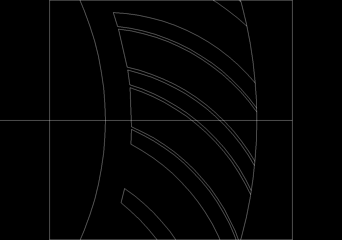
The teeth on the ring and pinion gears are cut in what is known as a Klingelnberg profile. These are essentially bevel* gears with a helical cut, but the helix has a pronounced curve. If you fit the two parts together, you can see that as you slide the pinion towards the center of the ring gear it will rock counterclockwise, and as you try to slide it away it will rock clockwise.
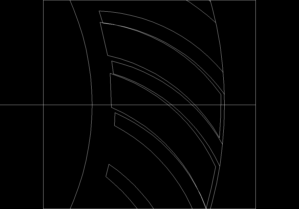
In the diagrams below, the light colored teeth are the ring gear and the dark teeth are the pinion. Notice that if the pinion is not centered, the teeth make contact at the upper left and lower right (too far in) or the upper right and lower left (too far out). In the middle diagram, there is even loading across the tooth face.
 |
 |
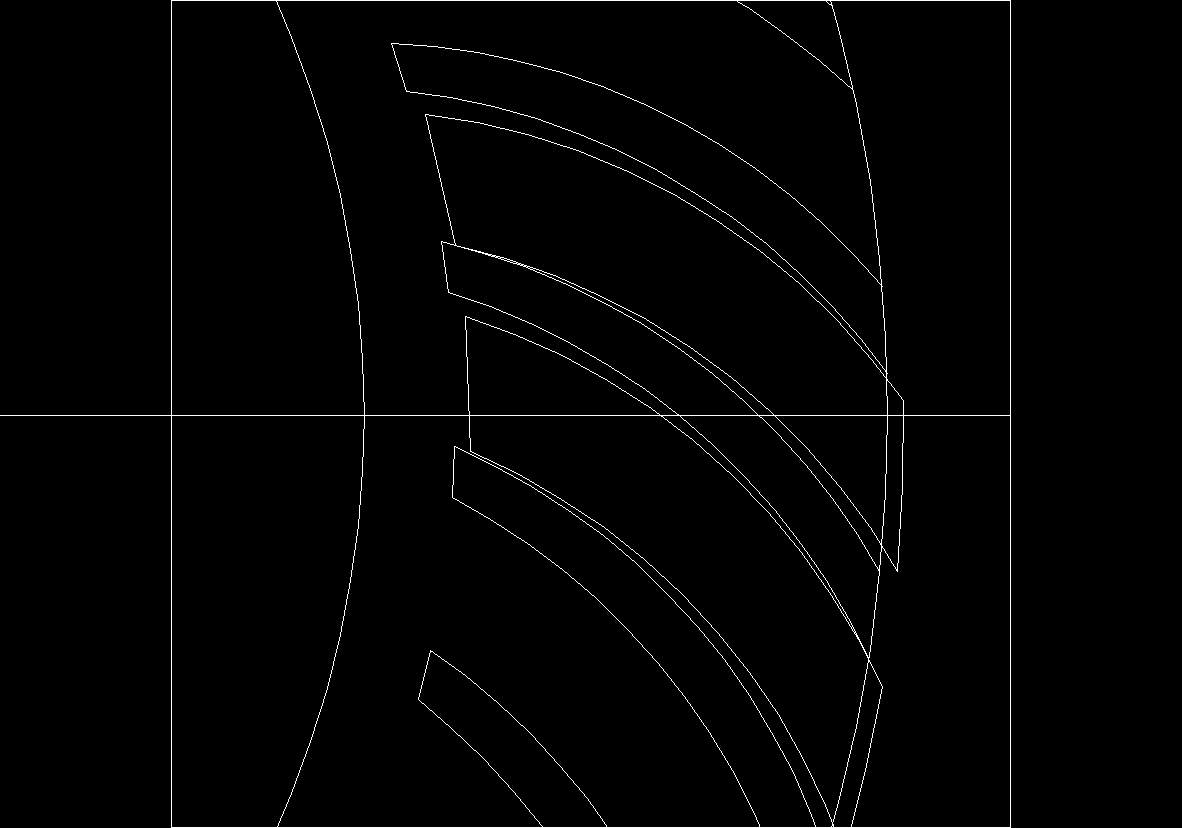 |
| Too far in - pressure is on the ends of the teeth |
Centered - pressure will be even across the tooth face. The gap represents the backlash. |
Too far away - pressure on the ends of the teeth |
There is only one distance (from the center of the ring gear) where the pinion is aligned properly, and the pinion shim holds the pinion in that one position. Positioning the pinion too close or too far from the ring gear will place all of the load on the edges of the teeth.
2. Backlash
With the pinion meshing properly, there should be a small amount of free play between the two gears.
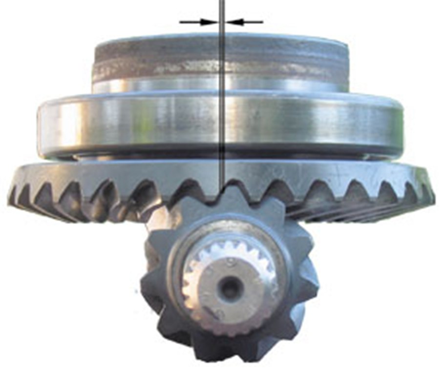
This is measured by immobilizing the pinion, rotating the ring gear and measuring the amount of movement. A shim under the tapered bearing controls the depth to which the ring gear seats in the housing. The closer it gets to the pinion, the less free play there will be. The specified free play at the gear teeth is about a tenth of a millimeter. If there's too much or too little distance between the gears, the teeth will wear.
3. Cover
Once the ring gear has been positioned in the housing properly relative to the pinion, the cover is installed so that it provides a certain amount of preload, or clamping force, to hold the ring gear in place.
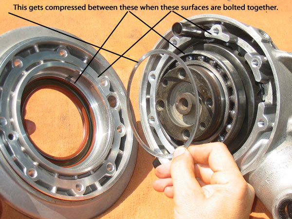
This is done with shims between the cover and the ring gear bearing. The flat areas on the cover and housing with eight holes are the mating surfaces. The distance that the bearing protrudes above this surface in the housing is compared to the depth of the bearing recess below the corresponding surface in the cover. Shims are selected to make the bearing taller (or make the cover shallower, take your pick) so there is a slight amount of interfecrence as the two are bolted together.
Evo Paralever
With the R1200GS, BMW introduced a new design for the final drive. The EVO Paralever is recognizable by the large hole through the middle. Where have we seen this before? Yes, the twin-shock Airhead final drives had a hole in the middle, where the rear axle went. With the single-sided swingarm there is no longer a separate axle, of course, but design similarities between the Twin-shock final drive and the EVO Paralever go farther.
On the EVO, the small end once again has a needle bearing, so the ring gear bearing cannot be preloaded. Axial position of the ring gear is now controlled entirely by the ball bearing at the wheel, and the needle bearing does not (and cannot) contribute any axial load due as a result of the weight of the bike. Those axial loads on the main ball bearing, therefore, are eliminated. Furthermore, there are only two clearances to shim: the pinion and the backlash.
That ball bearing is held in the cover, and the backlash is controlled by positioning the cover with shims. Without preload on the ring gear, the inherent play in the bearings can be felt as a tiny bit of looseness in the wheel. This is normal; BMW specifies that up to 1mm of play can be measured at the rim before a final drive is considered defective.
The twin-shock Airheads also had a needle bearing on the small end of the ring gear, but axial position was controlled by a thrust bearing shim, much like the Airhead crankshaft is. Counting the pinion and cover bearing shims, these drives still had three adjustments to make upon assembly.
Further details about the EVO final drives are in a different article.
* The term “Bevel” means that the axes of the two gears intersect. A worm gear would be a different type where the pinion axis is tangential to the ring gear, and a hypoid gear is anywhere in between the two. Bevel gears (like BMW final drives) and spur gears (engine, transmission) have only rolling contact between the gear teeth. Hypoid and worm gears have sliding contact.
*Note: "Axial load" refers to loading which results from a force applied along the central axis of the gear. For example, the sideways loading on a car tire as you go around a corner. Forces which act perpendicular to the axis, or towards the centerline of the gear, are referred to as radial forces.
Index
