Early 6-speed transmissions
(Originally published in OTL)
The same basic transmission was installed on the R1100S, K1200RS/LT/GT, R1200C, and all R1150 models (the second-generation Oilheads and K-bikes with Motronic 2.4 and the revised pushbutton switchgear).
Externally, the covers are different for the K and Boxers due to different engine mounting, and the housings differ depending on whether the swingarm is mounted to it (most R-bikes) or to the frame (K, R11S and R12C).
Internally there are also some model-specific differences. The reverser mechanism on the K1200LT occupies the space where 5th gear usually lives, so there are only five speeds in all (the 4th gear ratio is changed to better bridge the gap). R1200C prior to the CL also came with only five speeds because BMW skipped 5th.
However, the overall design and shifting mechanism are common to all of these versions. This transmission design is unique in that it uses a dedicated gear just to drive the intermediate shaft, so the intermediate typically has seven gears in all (in other gearboxes, the input shaft drives the top gear). As on previous boxers since the /2 and possibly before, the drive gear is helical and all of the others are straight-cut.
This article only shows the six-speed versions.
Shifting
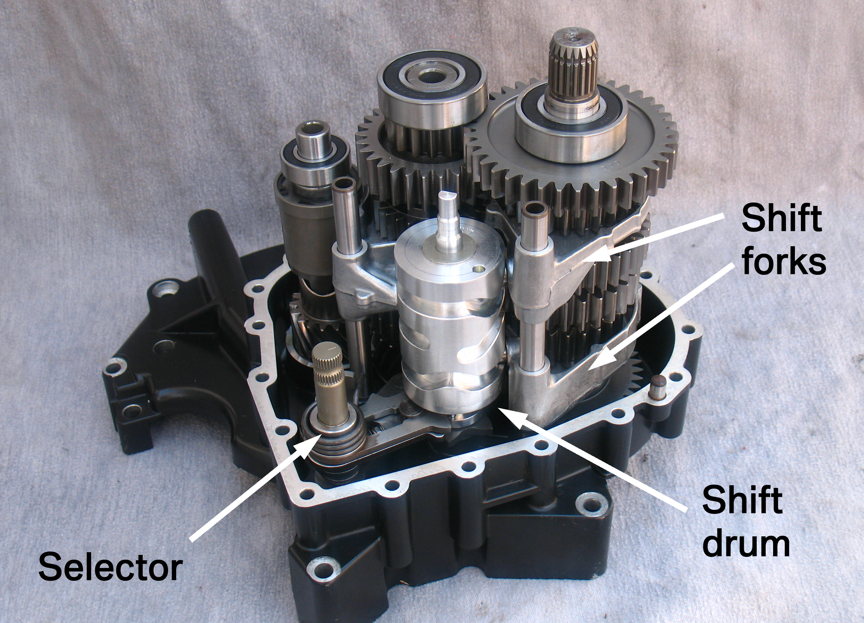
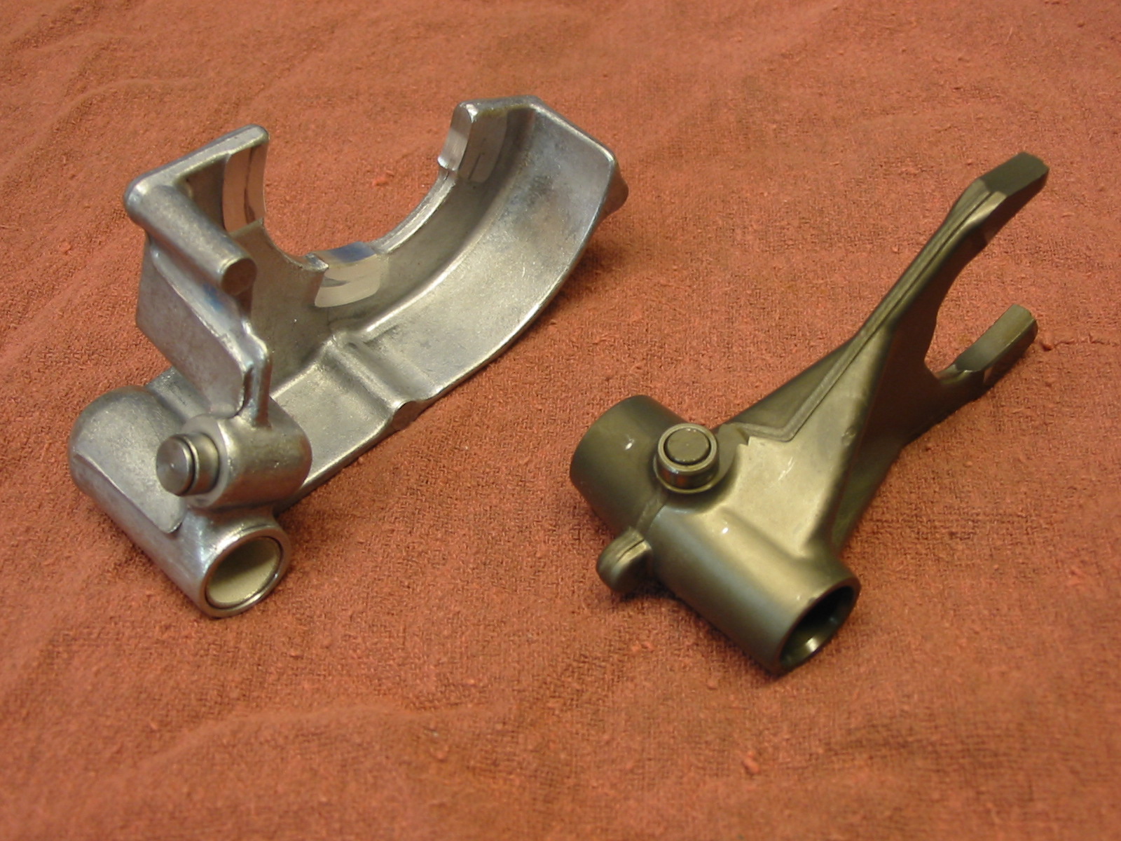
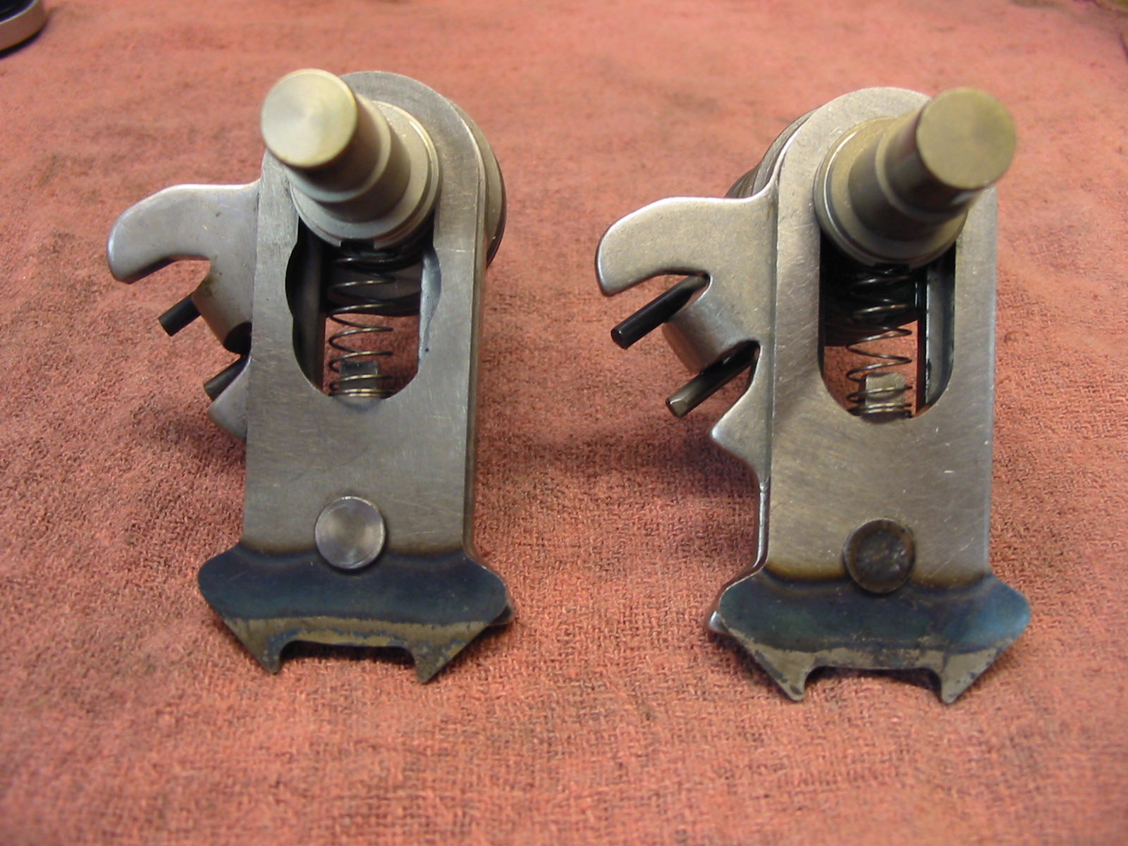
First let's take a brief look at the parts that do the shifting. The selector is basically the shift lever. When you rock the shifter up and down, it moves this back and forth. There's a ratcheting mechanism that turns the shift drum about 1/8 turn every time you shift.
The shift drum has a groove for each shift fork, so in each of its seven positions (including neutral) the shift forks are in different positions.
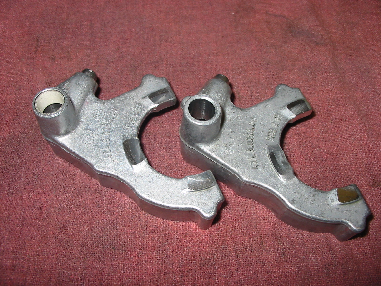
The three shift forks slide on rails and move according to their groove on the shift drum. Two of the forks are identified by arrows in the picture, and the third is on the other side of the drum.
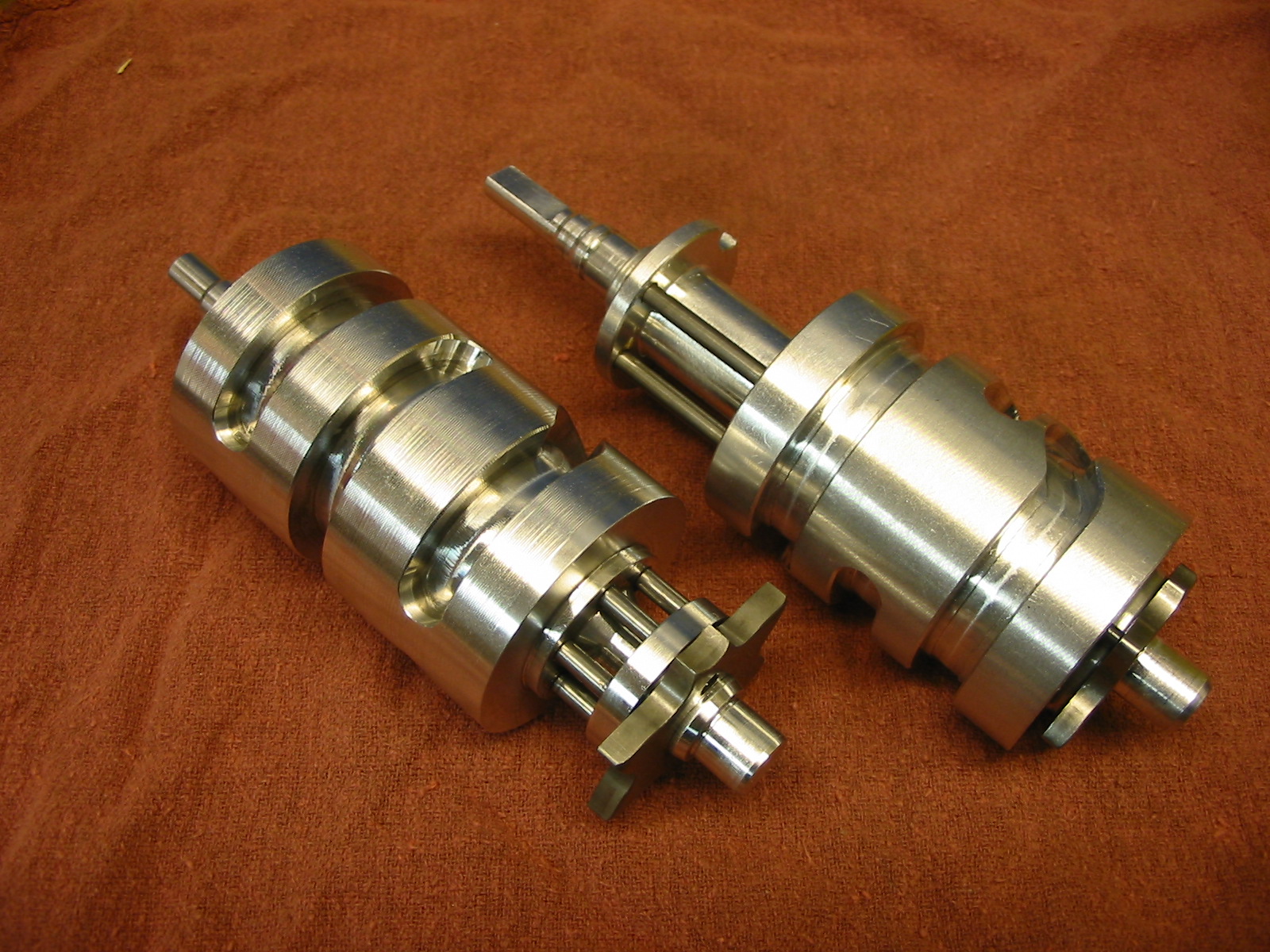
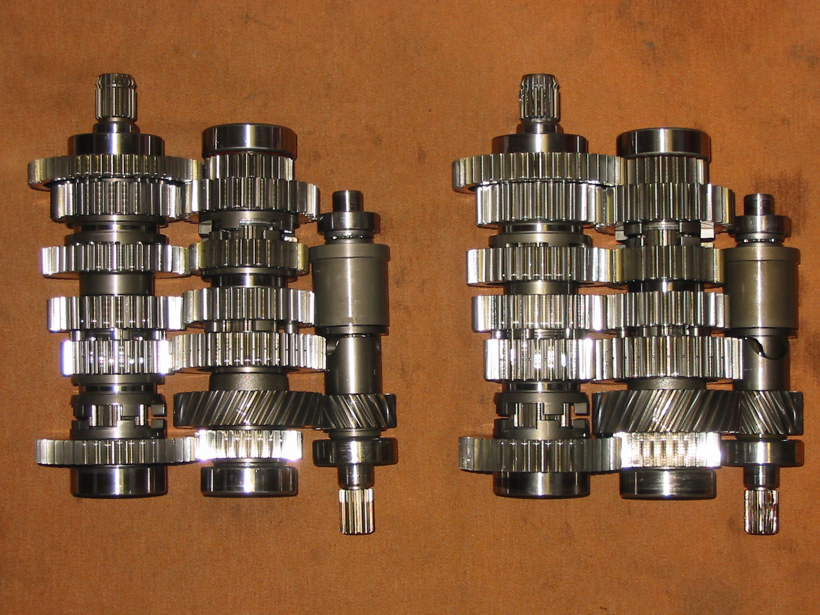
Shafts and gears
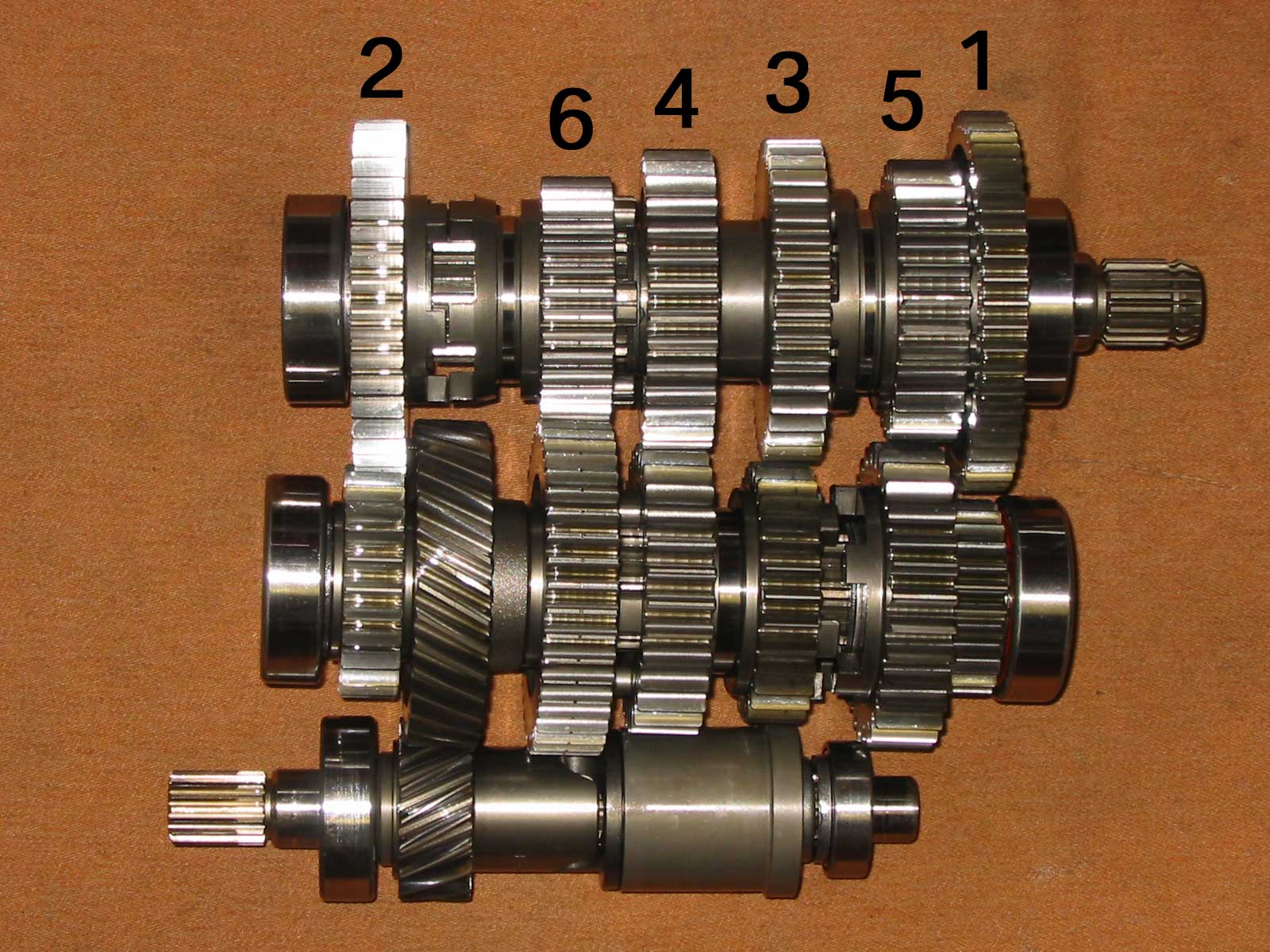
At the bottom is the input shaft with the clutch spline on the left. This is where the power comes in, and it drives the intermediate shaft via the helical (angled-tooth) gear. The stuff on the rear part of the input shaft is a shock coupling which lets the gear twist to absorb driveline shock.
The gear pairs of the intermediate shaft (center) and output shaft (top) are in constant mesh. One gear in each pair freewheels on its shaft and is engaged by locking against a neighboring gear which cannot freewheel on its shaft.
On the intermediate shaft, for example, 4th and 3rd gears act as one part, splined so they can slide sideways on the shaft but not spin. They slide to the right to lock 5th gear to the shaft, and slide to the left to lock 6th gear to the shaft (shown in the diagram). The square engagement dogs for locking the gears together can be seen between 6 & 4 and between 3 & 5. Between the two gears you can see the groove for the shift fork which does the sliding work.
The output shaft gears have similar grooves and engagement dogs. 6th gear slides to the left to engage 2nd, and to the right to engage 4th. 5th gear slides to the left to engage 3rd and to the right to engage 1st.
All of these combinations obviously rely on only one gear engagement happening at once. For instance, in the diagram the shift fork (arrow) is pushing the 3-4 intermediate gear to the left, locking 6 to the shaft. Because the mating 6 is splined to the output shaft, power is transmitted from intermediate to output. 1, 2, 3 and 4 on the output will be spinning freely, as will 5 on the intermediate. If the intermediate 3-4 gear moves back to center, the intermediate 6th is once again free to spin and therefore will be unable to transmit power. The shift drum is what choreographs the engagements of the various shift dogs. The drum rotates and moves the three shift forks which each move a gear. Two forks must always be centered so that their gears don't engage on either side.
So when you're riding down the road, all of the gears are turning but only one pair has both gears locked to their shafts. The others all have one gear, on the intermediate or on the output, that are turning at a different speed than the shaft is. Locking this gear to the shaft during a shift - bringing it to the same speed - is the clunk you sometimes notice.
Before you read farther, try to visualize what's happening in neutral, at a standstill with the engine running. Ready? OK, the input shaft is spinning the intermediate, through the drive gear. So the intermediate is turning, meaning that the 1, 2, and 3-4 gears are spinning with it. They in turn are spinning their freewheeling counterparts on the output shaft. The output shaft, though, isn't turning because the rear wheel isn't, so 5 and 6 on the output are also stationary (because they are splined to it). Their counterparts on the intermediate shaft are therefore stationary, with the intermediate shaft spinning away inside them.
Shimming is mentioned constantly with transmissions and final drives. What is it? Usually when shafts are supported by bearings in any kind of housing, the amount of axial room that the shaft has to move in is controlled by shims of some sort. In the past I talked about this in final drives, so this is the transmission part.
Transmission housings are two parts, a case and a cover. Sort of like a jar and a lid, except the seam between them can be anywhere, meaning that you can have equally-sizes halves if the designer wants. Nevertheless, the larger half is considered the case and the smaller half is the cover. All three shafts of these (and most other) transmissions are held by ball bearings, one end in the case and one in the cover, and shims are added somewhere to eliminate the extra space. Traditionally, measurements for shimming have been done like this:
Traditional shimming [this can be a sidebar or taken out of the main stream, as it is background info].
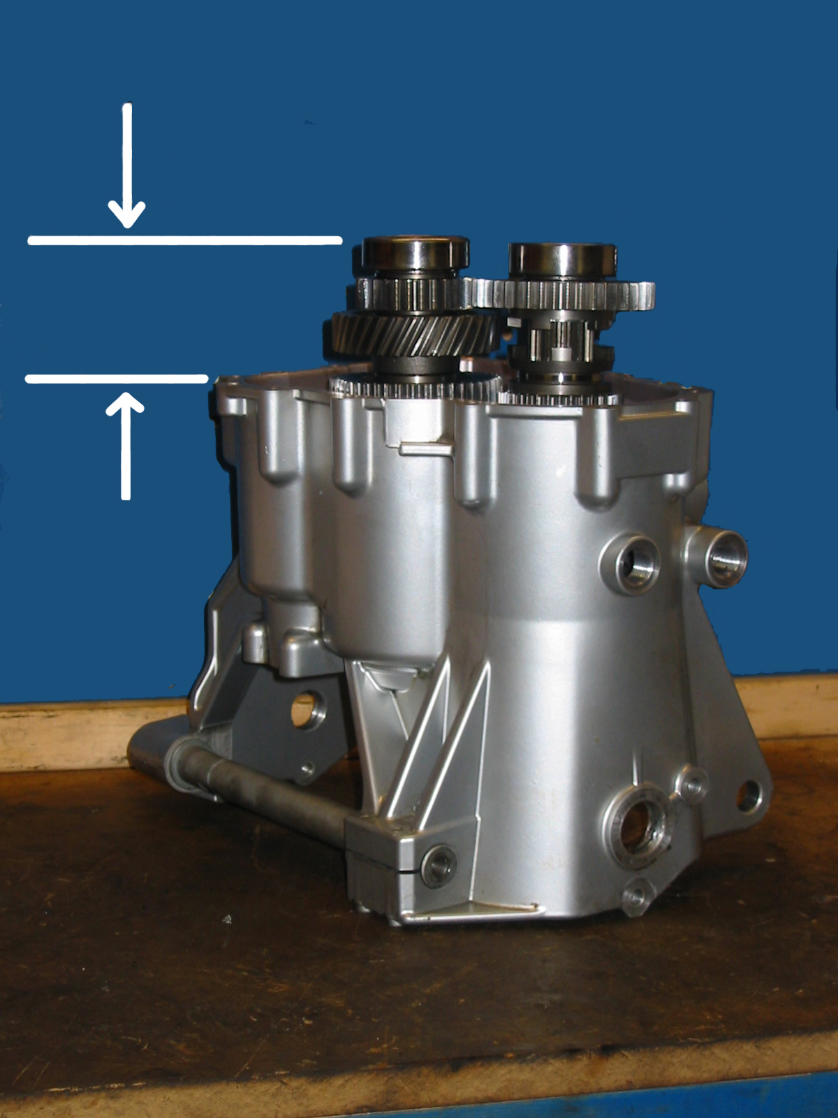
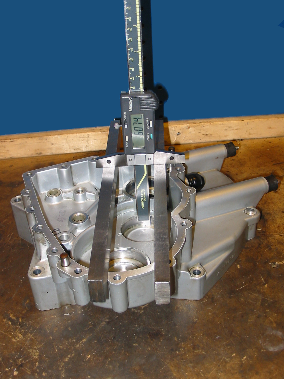
This has all changed with the six-speed. With the new method, actual measurements involving the cover and housing (as shown in the pictures) are things of the past; the cases and covers are assumed to be a given dimension and the shaft assemblies are built to a preset length using shims under the bearings.
As you can imagine, proper shimming therefore depends on the cases being made to specification. Is this happening? It depends on what you want to accept. The allowable variation in shaft assembly length is 0.05mm, and shims are available in increments of 0.025mm (this is really a very small increment by any standard, but this is BMW). Using the input shaft bearing bores as an example, the depth I have measured on covers varied by 0.03mm and the cases varied by 0.06mm, for a total possible variation (with these components) of 0.09mm. Figured the same way, the intermediate and output shaft bores also varied by 0.09mm.
So you might think that the variation in the housings overcomes the required shimming precision. Numerically it does, but in reality, these trannies are not subject to the same shimming-related problems that befell the 5-speeds. Rounded shift dogs and worn forks just don't happen. These are very robust transmissions.
The EVO 6-speed
There was one design update during the life of this transmission. The EVO transmission was introduced on Boxers for the 2003 model year and on K1200RS/GT for 2004.
EVO gears are narrower with a deeper profile. The shift forks have teflon bushings to help them slide on the shift rods, and the selector assembly is cut differently (better finish on the ratchet and different material thicknesses). Due to the width change, the EVO gearset is lighter at 7.8kg versus 8.4kg for the earlier version. Earlier bikes with shifting difficulties can be upgraded with the newer selector shaft. The gears and forks are upgradeable also, but not cost-effectively.
The three main housing types are R1100S/R1200C, R1150, and K1200. There are two first gear ratios and two 6th gear ratios, two colors (R1150 only) and of course the EVO update. These details can be seen in the suffix of the gearbox ID code.
| First letter | Second letter | Third letter | ||||
|---|---|---|---|---|---|---|
| F | Early K1200RS | A | Original | A | Silver | Early K & C |
| G | Early Boxer | B | Spare | B, C | Silver | Early S |
| H | Early K1200LT | C | Replacement | E, L | Silver |
Boxer early std |
| J, K | Silver/black | Boxer early sport | ||||
| G | G | Black | Boxer early std | |||
| J | EVO Boxer | L, M | Silver/Black | EVO enduro | ||
| K | EVO LT | N, P | Silver/Black | Early enduro | ||
| R | Black | Rockster, special finish? | ||||
| S | Silver | Boxer EVO std | ||||
FAA - 2002 K12RS
HAA - early silver K12LT
GAA - 98, 99, early R1200C BB, BB, DM
GAB - 99, 99, 00 silver R1100S BB, BB, EH
JGB - TPC 1st replacement R1100S silver
JBC - TPC 2nd replacement R1100S silver
GAE - early silver R1150GS
GAF - black R1200C (eBay)
GBE - 02 silver R1150RT fluidj
GAL - 02 silver Roadster tall 6th Phil Kavanaugh
GAL - 02, early silver R1150R
tall 6th BB, Mihalka
GAN - 02 Adventure
JAE - 03 R1200CL silver on eBay
JAH - black
JAK - 03 black sport GS Neil
JAL - EVO silver Adv.
JAM - 03 black Adventure, RT-P
JAR - Rockster, black (supposedly Sport)
JAS - 04 silver R1150R tall 6th
GAB on eBay, not from an S?
GAE => up to 2003, silver, normal 1st, Serie (= long 6th)
GAF => up to 2003, black R1200C
GAG => up to 2003, black, std
GAJ => up to 2003, silver, normal 1st, short 6th
GAK => up to 2003, black, normal 1st, short 6th
GAN => up to 2003, silver, short 1st and short 6th (only GSA)
GAP => up to 2003, black, short 1st and short 6th (only GSA)
JAE => EVO silver
R1200CL
JAH => EVO black standard
JAJ => EVO silver Sport
JAK => EVO black Sport
JAL => EVO silver Enduro
JAM =>EVO black Enduro
JAR => EVO Rockster Sport
JAS => EVO silver standard
Ratios
The Enduro gearbox (lower 1st and 6th) was used on the GS Adventure and supposedly on some R1150RT-P authority bikes. The lower 6th by itself was the basis for the Sport gearbox, and was used on the R1150GS Sport, some R1150R and R1200C models, and most K1200 models (where it acts like 5th on the LT).
The EVO ratios weren't significantly different. Some EVO gear pairs had different numbers of teeth than pre-EVO, but the ratios were within half a percent of the originals. Primary drive is 18/34 for both the early and the EVO. This table shows the intermediate to output gear ratios and the overall transmission ratio.
| Original | EVO | ratio | |
|---|---|---|---|
| 1 Enduro | 16/38 | .22 | |
| 1 Regular | 22/45 | 26/53 | .26 |
| 2 | 25/40 | 25/40 | .33 |
| 3 | 30/38 | 30/38 | .42 |
| 4 | 26/27 | 29/30 | .51 |
| 5 | 30/27 | 31/28 | .59 |
| 6 Short | 30/24 | 36/29 | .66 |
| 6 Long | 33/23 | 43/30 | .76 |
How can I have both the low first and the tall sixth?
BMW never made this configuration. Changing a gear ratio means replacing the gear on the output shaft and replacing the entire intermediate shaft with one having the ratios you want, totalling about $1100 to $1150 in parts plus seven to ten hours of labor in all. However, there were no transmissions produced with the short first and the tall sixth, so there simply is no intermediate shaft available for that combination.
Creating the aforementioned ratio involves building a custom intermediate shaft. The first gear wheel is machined as part of the shaft, so you will have to start with the intermediate shaft from an enduro transmission. At the other end, the second and drive gears are pressed on, so they have to be pressed off using about 15 tons of force. Once they're removed, the sixth gear wheel can be replaced by one from a standard transmission, and then the two end gears are pressed back into place. Of course, this means you need to have a donor intermediate shaft to supply the tall sixth gear.
I've done several of these conversions.

